Introduction
I’ve been doing quite a lot of work with rotary encoders lately. Testing the code of written for the AVR chips becomes quite a hassle when you need to turn a rotary encoder and just the right speed and duration to produce a good signal to debug against. I found this schematic somewhere on the web that automatically produces a quadrature signal. I’ve bumped it against a 555 timer with trimpot to make an adjustable timing for it.
For those that don’t know what a Quadrature Encoder is, its simply a device that outputs two signals that are 90 degrees out of phase with each other. WikiPedia has some decent information about quadrature, along with how they are used with rotary encoders. Briefly however, the below image shows how quadrature works. As a bonus, this is the actual output from the Quadrature Generator.
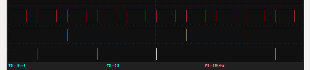
Output from the Quadrature Generator, captured on Bitscope Logic
The red trace it the clock input from the 555 timer, and the other two traces are is the quadrature. Notice they are 90 degress out of phase of each other, taking four clock cycles for a full rotation.
Schematic
So i must apologise for this schematic. I had it beautifully drawn on my Galaxy Note 10.1, but the Eagle component libraries have different pin locations then what I had used. So the net connections are all over the place. Hope the idea is there though…
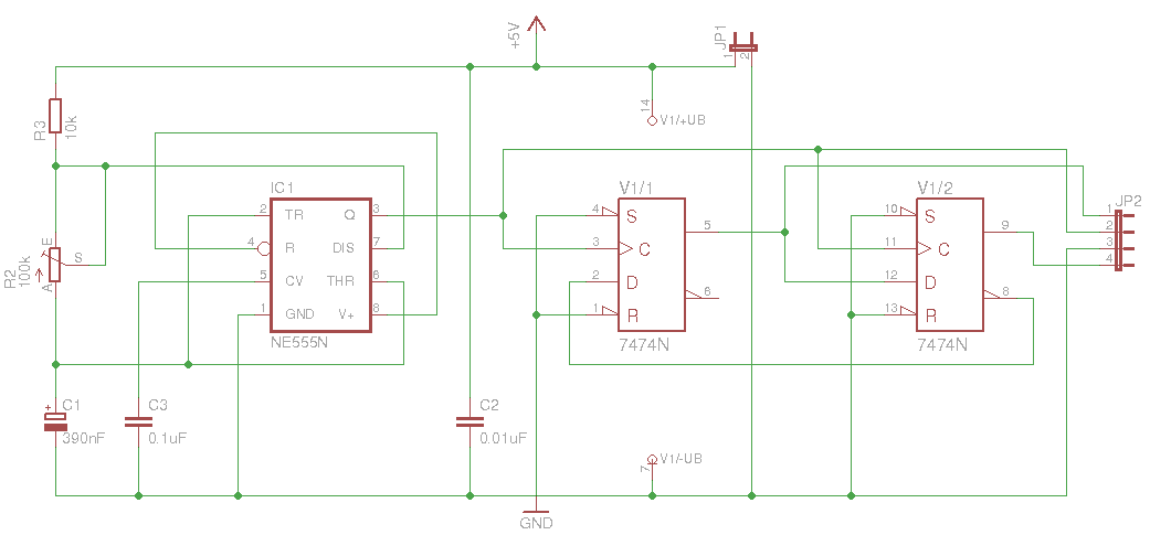
Schematic, Flip-Flop is a 74LS74, click for larger version
Download the Cadsoft Eagle schematic here
The 555 timer simply provides a variable clock source (By adjusting TrimPot R2) to the 74LS74 Dual D-type Flip-Flop. The 4 way jumper provides an connection for the clock, output 1, output 2 and a ground connection (Making it easy to debug). The 2 way jumper is the +/- supply. The 74 series chips limits the Vcc to +5V, but replacing it with a CMOS 4013 flip flop will allow voltages up to around 15V (With a max speed of about 2Mhz).
Bill of Parts
- 74LS74 Dual type Flip-Flop
- NE555 Timer
- 100k trimpot (I’ve used a horizontal mount type)
- 10k 1/4W resistor
- 390nF ceramic cap
- 0.1uF electro cap
- 0.01uF ceramic cap
- 2 way jumper header
- 4 way jumper header
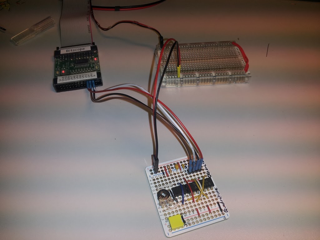
Testing the output with the bitscope