Downloads
Source Code (91KB)
The above is stable code for this Project, but new features may be added in my SVN Repo.
Introduction
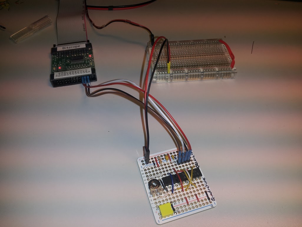
Over a year ago, I purchased a Saitek Cessna Trim Wheel to complement my Flight Simulator setup. At first it was a decent enough product, but over time took a number of USB resets to be recognised by Windows. Then not long after the warranty expired, it completely stopped being enumerated and would no longer work no matter what i tried. In stead of binning the device, and inspired my some of the mods that Tom at FSX Times gets up to; i decided to pop it open and see what i could do to repair it.
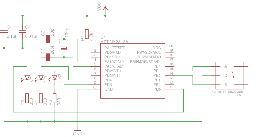
Inside, it turned out to be a fairly straight forward setup. I small MCU, connected to an optical rotary encoder, using a plastic disc with notches cut around the outside to provide the mechanism (which in turn was connected to the actual trim wheel). After tracing out PCB tacks to produce a rough circuit diagram, it was time to see if the issue was with the MCU, or the optical RX/TX components.
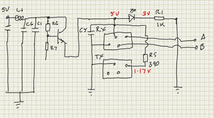
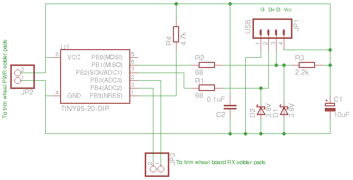
Rough sketch up the Saitek circuit
The TX part of the encoder looked like a standard IR emitter, given only two of the four pins where connected, and it was running at 1.17V (Down from 5V via the 390 ohm resistor). The Opto Encoder however required a little more research, as i had not heard of these devices. I ended up coming across the HLC2701 IR detector. Reading the specs on this made me smile, as it outputs in quadrature; something i had been working with very recently making life a little easier. Given that the entire device wasn’t registering within Window, i figured it meant that the MCU would need to be replaced with my own. This also meant working with a USB interface (Something i hadn’t really done up until this point).
Two test wires soldered to the IR Detector
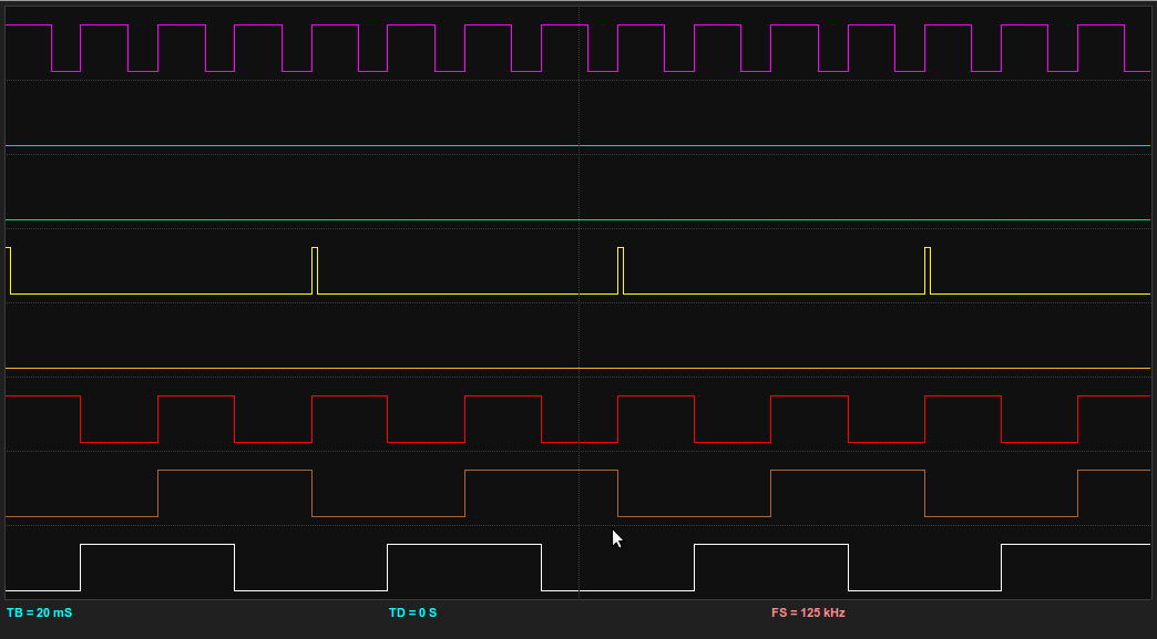
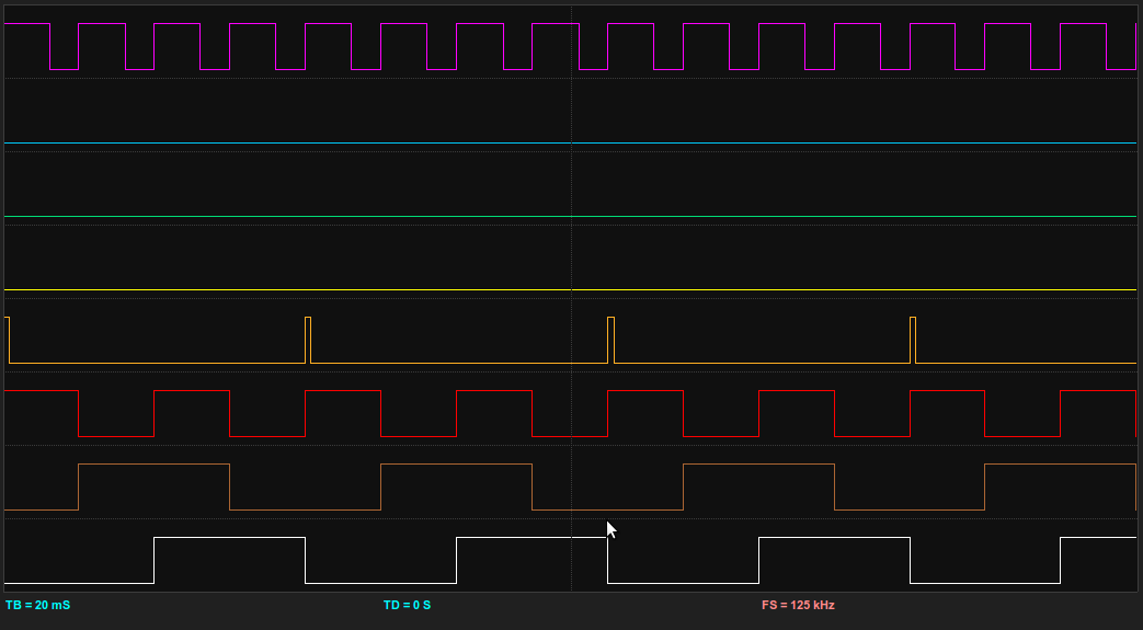
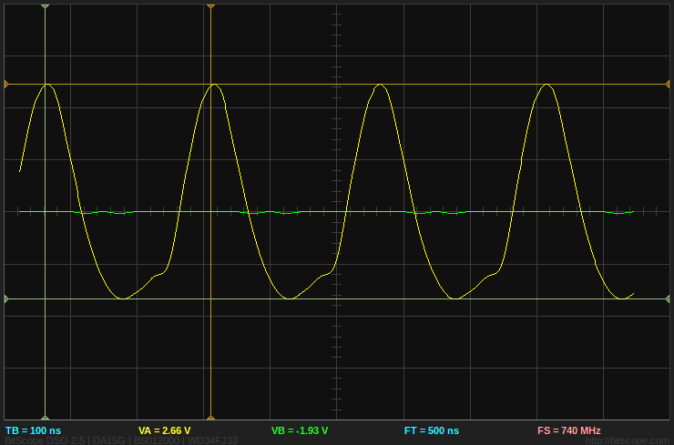
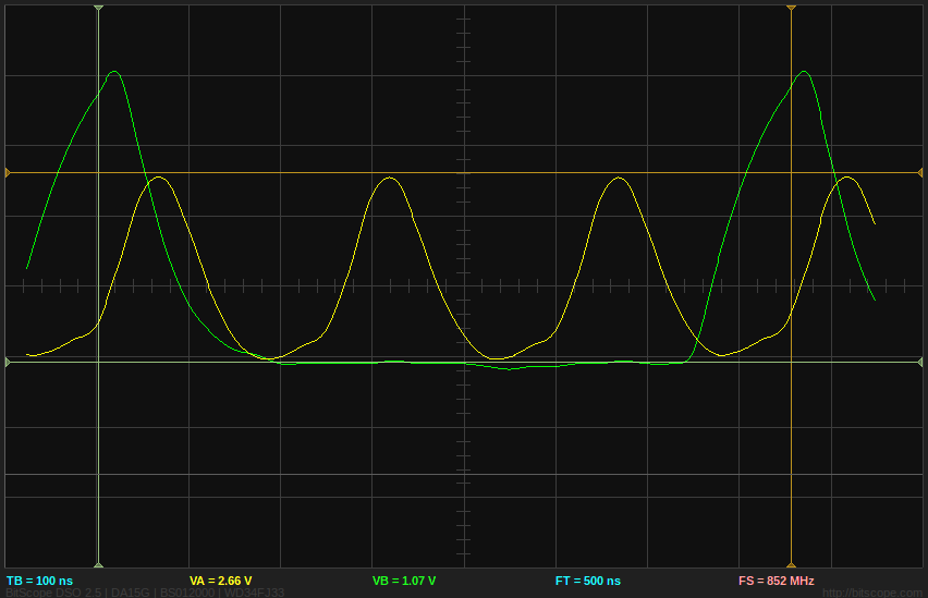
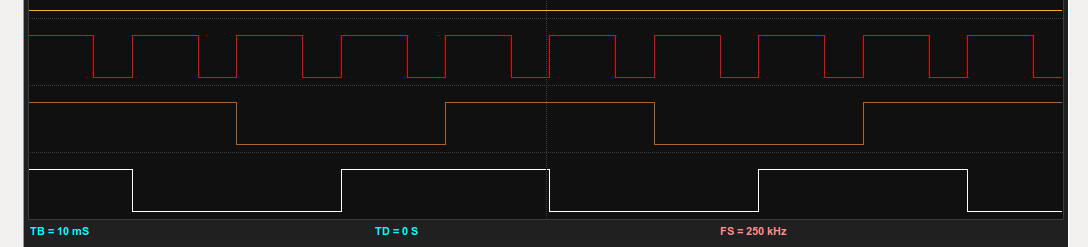
Skipping ahead a little bit, i decided to check the RX/TX part of the optical encoders. Being able to use those meant not having to create my own mounting hardware if by using the current board with mine piggy backed onto it. First up, I soldered a couple of wires to the output (A & B) of the RX IR detector. This allowed me to easily hook it up to my Bitscope, and within a couple turns on the Trim Wheel, was registering a quadrature output from the two signals. With these confirmations, it was time to think about how I could piggy back my own device onto the the optical encoder, and how to fit it in the casing.
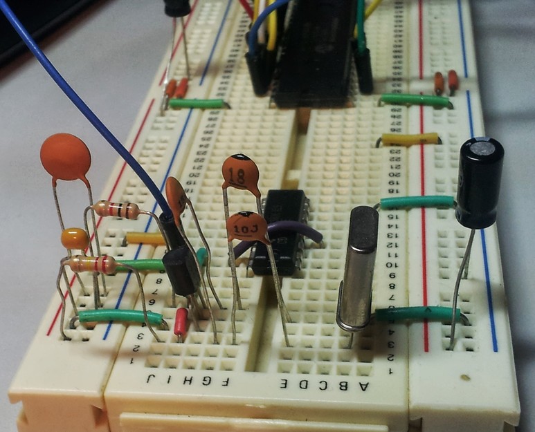
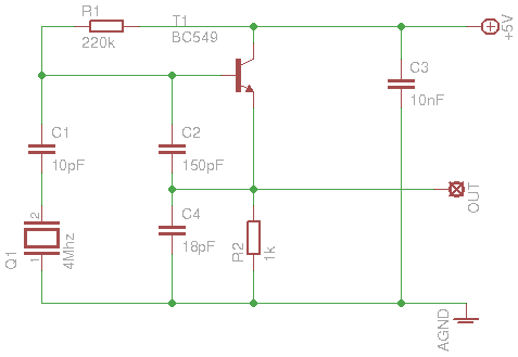
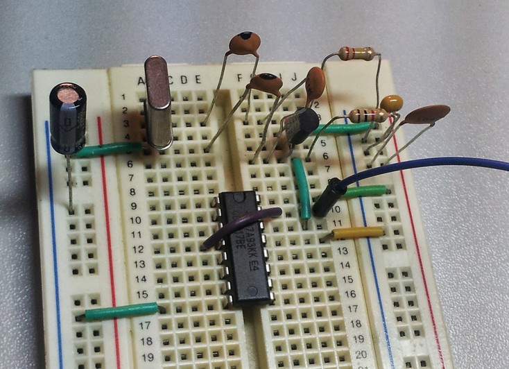
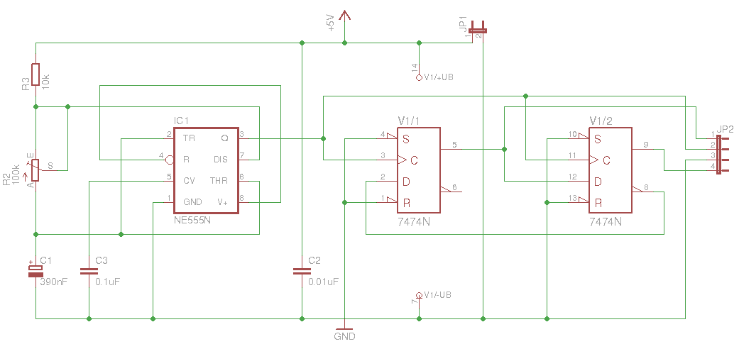
Being the impatient sort, i decided to whip up a test circuit circuit based on my Rotary Encoder Example. My biggest concern at the this point was trying to get the ATTiny85 to talk to Windows as a USB HID Joystick. The quicker i had a playground to start testing with, the better.
Testing the rotary encoder of the function was the quickest success I have had with any electrical project! The setup was receiving the quadrature output of the encoder on my first attempt, and re-invigorated me to pursue this hack.
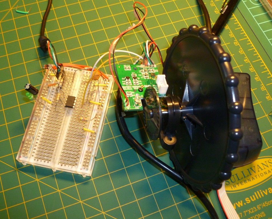
Breadboard circuit hooked up to the Trim Wheel test wires.
Next up was getting the circuit to talk to Windows! The original Saitek device talks to Windows via a Saitek propriety USB joystick driver. At this point, i didn’t know much about Windows USB drivers, so opted to use a Windows USB HID Joystick arrangement. This is essentially a descriptor file that lives on the USB device, that tells Windows what kind of data to expect, and what it means in terms of user input. This bypasses the need to a custom driver for every device (Mouses, Keyboards and generic joysticks all use this functionality).
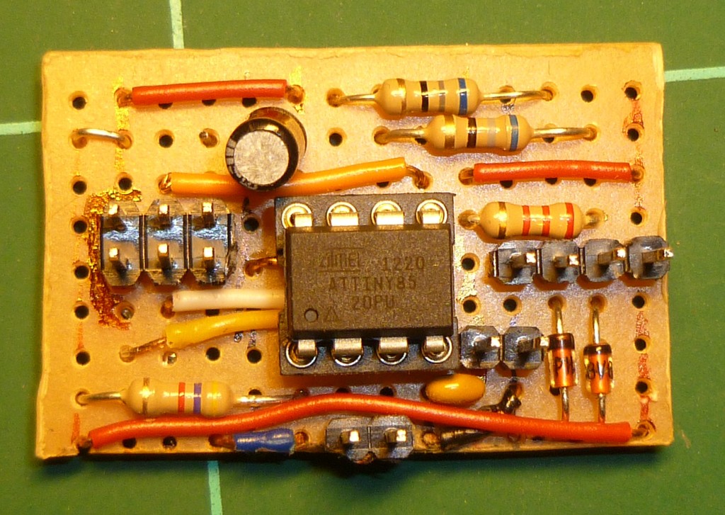
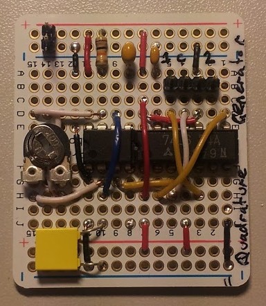
Replacement prototype
While researching USB HID and how this would work with an ATTin85 device, i came across the V-USB project. This is essentially a USB 1.1 all firmware library for AVR’s, that would seem to fit the bill perfectly. I also came across this project from Code and Life using V-USB that provides the entire base template for my project (Both schematic and code!). Without both of these sources, i doubt this project would have ever seen the light of day!
Fast forward through a lot of hacking and breaking things to get the HID descriptor working in Windows (And never plug a V-USB device into a USB3.0 hub, it just won’t work!), and I had a reasonably working replacement for the Saitek MCU. The next few photo’s will show how to interface my replacement MCU with the Optical Encoder.
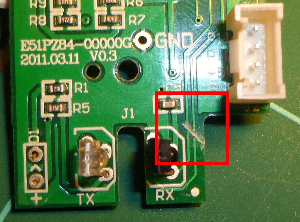
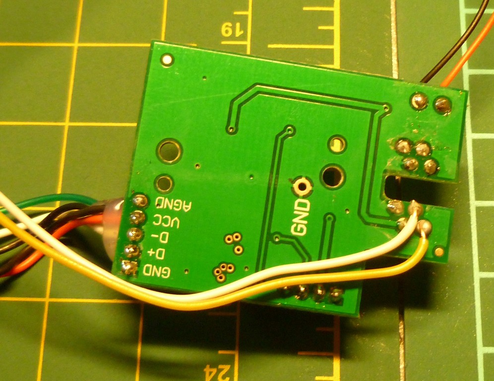
The tracks between the RX pins and the MCU must be cut
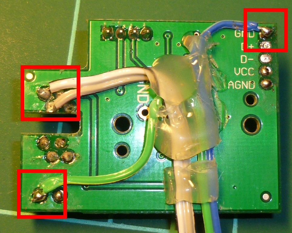
A & B output connections (White & Grey), Ground (Blue) and +5V (Green) connections.
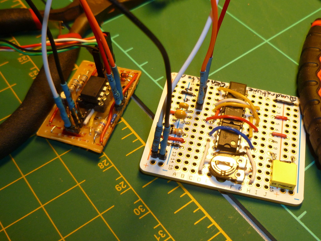
Testing the board prior to installation
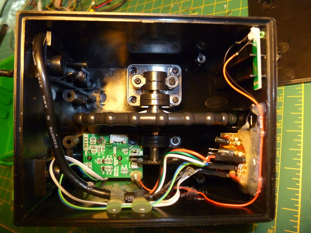
After some thorough speed testing using my Quadrature Generator module and some testing in FSX, it was time to mount the new board in the Trim Wheel case, and put the thing to work. Although I had soldered the wires directly to the Saitek MCU board, i decided to use pin heads on my proto board in case i wanted to swap it out for a different version later. This also made it much easier to mount my proto board in side the case, as i didn’t have to connect the cables until it was all glued in place. The below image shows my final placement for the board, and the oodles of hot glue I used to hold it in place.
Todo: Insert picture of HID Joystick in Windows
Conclusion
This project enabled me to revive my Trim Wheel which other wise would have been thrown in the bin, saving me $60, with about $7 worth of parts. This also gave me the knowledge i needed to develop USB devices, and led me to work with FSX SimConnect to enable much richer devices, which i’ll post about in the future (Or see the sneak peak picture below).
My next version of the Trim Wheel will be tightly bound to FSX, instead of being a USB Joystick. This will allow me to pass back to the device the current location of the simulators trim wheel, removing the ‘absolute value’ issues that joysticks have. (Basically where the Trimwheel snaps back to its previous location prior to disabling Auto Pilot).
If there is anything I’ve left out here that you feel is needed to complete your own project, please let me know and i’ll update with greater detail.
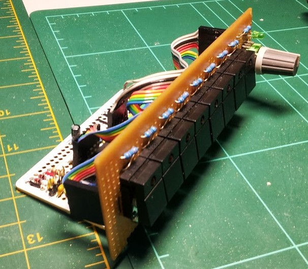
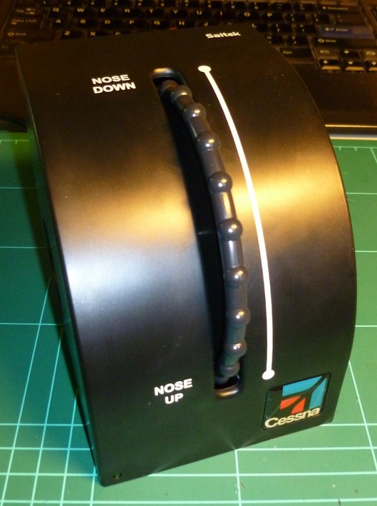
Sneak peak of my up coming FSX project: The Audio Comms Selector
Gallery of All Pictures For This Project
[flagallery gid=4]