Introduction
This example is about using Rotary Encoders with AVR chips. In provides a brief look at what they are, and how to use them.
While searching the web for how to use rotary encoders, I came across a number of tried methods. Nearly all of them though used the hardware interrupt pins on the chip though. As i use these primarily for USB, i could not spare them for a rotary coder (let alone if when i wanted to use multiple rotary encoders!). For this reason, i developed my own solution using the Pin Change Interrupts (PCINT). These are similar to hardware interrupts, but trigger when any of the Pins enabled to use PCINT change. It is then up to the developer to discover what pins actually changed, and what the changes are.
Rotary Encoders
As usual, Wikipedia has the best definition of a Rotary Encoder:
A rotary encoder, also called a shaft encoder, is an electro-mechanical device that converts the angular position or motion of a shaft or axle to an analog or digital code.
Rotary Encoders come in many shapes, forms and output types. The simpliest rotary coder looks like a potentiometer, but is continually turnable. Other have dual shafts (or two inputs), and can come with switches in built (depresses the rotary encoder closed the circuit). Some are made to be connected to large machinery and turned via engines and what not.
The ‘analog or digital code’ describes how the rotary encoder actually encodes the information we have received via input into the rotary coders (i.e. turning the encoder). The type of output we are interested in for this example are those that output in ‘Quadrature’.
Quadrature is two signal that is 90 degrees out of phase with each other. That means that the direction of the turn can be indicated by which of the signals changed first (and the 2nd confirming the turn). The angular speed of the turn can also be indicated by the duration of the pulse. However, for this project, we are only going to look at which way the encoder is turning.
To learn more about quadrature, i suggest reading my previous post detailing how to make a Quadrature Generator.
Example Code and Schematic
For this example, i’ve used the ATTiny2313 chip. Any AVR will do, but you will need to update the code with the correct ports to make it work with other variants (Even the ATMega’s). The 2313 series is a cheap chip for development, but with only 2K of program memory, it seriously limits what you can do with it (Even the newly released 4313 with 4K of PROGMEM is very limiting).
The example im showing here has the rotary encoder as the input, a 3 leds as outputs. The leds function like this:
- LED1: Indicates the rotary encoder was turned in a direction.
- LED2: Indicates the rotary encoder was turned in the opposite direction to LED1.
- LED3: Indicates that an pin change interrupt has been received by the chip.
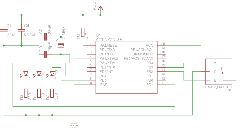
Download: The Eagle schematic here
Below is the code for the example. This code can also be viewed on my SVN Repo. The avr-gcc Makefile is also available in the SVN repo.
#include
#include
#include
#include
#include
#define F_CPU 12000000
#include
#define DEPRESS_TIME 1
#define sbi(sfr, bit) ((sfr) |= _BV(bit)) // Set bit
#define cbi(sfr, bit) ((sfr) &= ~(_BV(bit))) // Clear bit
#define xbi(sfr, bit) ((sfr) ^= _BV(bit)) // Flip bit
#define rbi(sfr, bit) (((sfr) >> (bit)) & 0x01)
volatile uint8_t pcIntCurr = 0;
volatile uint8_t pcIntLast = 0;
volatile uint8_t pcIntMask = 0;
volatile uint8_t timer0_ovf = 0;
volatile uint8_t time_rot = 0;
void doInt();
int main() {
cbi(DDRB, PCINT2);
cbi(DDRB, PCINT3);
TIMSK = (1<
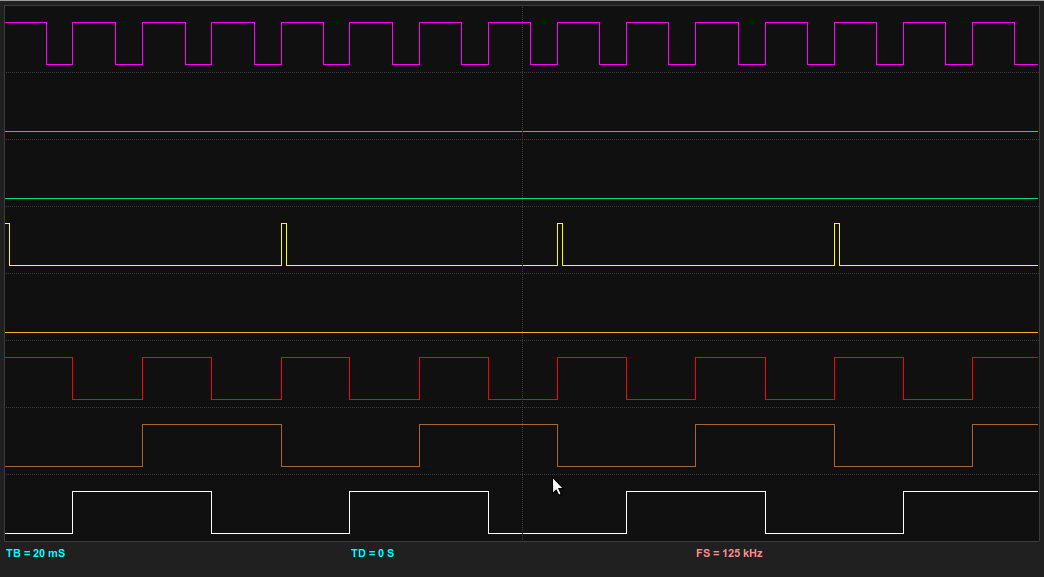
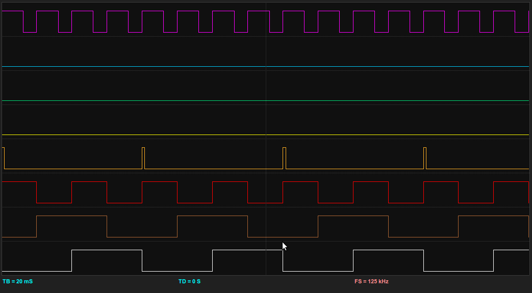
Conclusion
Here are the Bitscope Logic outputs dumps for the rotary being turned in either direction. This is actually using the Quadrature Generator to provide input. This is a great way to test the rotary code, and is also great for testing how fast the MCU can detect changes. The definition of each of the traces are:
- WHITE - Rotary Encoder A Input.
- BROWN - Rotary Encoder B Input.
- RED - Clock signal from the Quadrature Generator.
- ORANGE - A DIR2 turn event occurred.
- YELLOW - A DIR1 turn event occurred.
- PURPLE - A Pin Change Interrupt (PCINT) occurred.
Gallery of all images in this post:
[flagallery gid=3]