Category Archives: Examples

Geeetech FX2LP CY7C68013A USB DevBoard

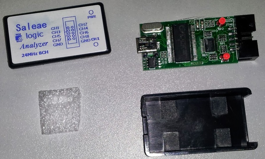
I recently purchased a Geeetech (clone/knockoff) off ebay for a small $5, and wanted to test its functionality for use with my Flight Sim devices. The CY7C68013A is the same chip used in the Salae logic analyzer (and ripoffs), so figured it should have pretty decent performance.

Despite being used in quite a number of logic analyzer type projects, I couldn’t find any decent beginner information for it, so this will try and fill the gap; especially for windows users.

This first part post will describe settings up the environment, and the second post will delve into the features of this dev board and chip.
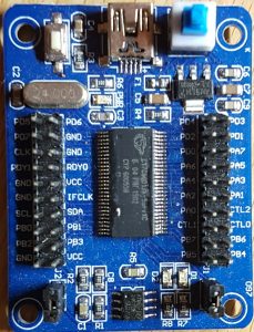
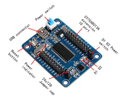
The CY7C68013A

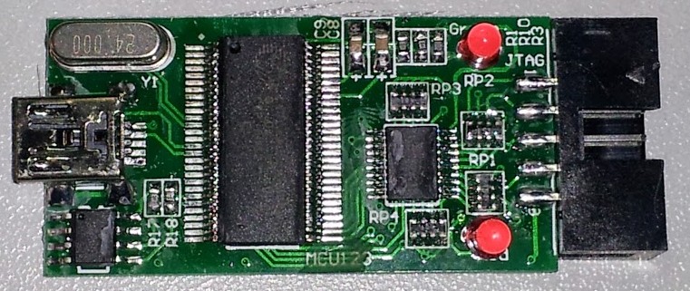
The chip board presents 20 GPIO ports (With 2 interrupt pins), a i2c bus, dedicated USB pins, and a couple of ancillary pins. Its work noting that the 56pin SSOP doesn’t have a serial port, which is a bit disappointing.

The board itself has 2 LEDS, D1 and D2 attached to the PA.0 and PA.1 ports respectively. This ties up both the interrupt pins, so will only be useful for initial testing.

Programming the chip is done via the EZ-USB software provided by Cypress (Or its open-source equivalent which only seems to be available on linux). The software can download a compiled .hex file directly to the RAM of the chip (Lost after reset), or the EEPROM provided and accessed via the i2c port. Data on the EEPROM will survive resets, but the chip must be disabled by adding J2 on the board before trying to reprogram it again.

Installing Software and Setting up Environment

  1. Install Cypress Dev Kit (CY3684Setup.exe)
    • Install inf file from C:\Cypress\USB\CY3684_EZ-USB_FX2LP_DVK\1.1\Drivers\Win8.1\x64 (Go into folder for your OS version, right click on inf file, click install)
  2. Install the CY7C68013 Dev Tools from fx2lp.exe
  3. Plug in the Device, driver will auto install
  4. Install sdcc
  5. Install make
  6. Install TortoiseSVN (Optional)
  7. Install  Eclipse (Install with C/C++ Development)
  8. Edit system path:
    • Run “C:\WINDOWS\System32\control.exe system”
    • Goto Advanved system settings -> Environment Variables
    • Edit ‘Path’; Add:
    • C:\Program Files\SDCC\bin
    • C:\Program Files (x86)\GnuWin32\bin
    • C:\Cypress\USB\bin

Setting Up Eclipse and Importing Code

The credit for ‘gtfx2lplib’ must all goto here: https://github.com/ubixum/fx2lib

I’ve taken the code base from there, removed whats not needed and modified it to suit the Geeetech dev board. I’ve renamed the library to ‘gtfx2lplib’

  1. Download gtfx2lplib.zip
    • Extract it somewhere
    • Most up to date source available from NewioIT WebSVN
  2. Import gtfx2lplib into Eclipse:
    • New -> Makefile project with existing code
    • Once import, create build targets ‘all’ and ‘clean’ (If they dont exist)
    • (Right click gtfx2lib, goto ‘Build Targets’ – Create; name one ‘all’, and one ‘clean’

Building Code and Deploying

Now we just have to build the code, and upload an example to the dev board. The below will write the code to the RAM, which will be lost after reset.

  1. Right click on the ‘all’ build target and build it
  2. Check the console to make sure everything compiled correctly
  3. Run CyConzole EZ-USB (Start menu or “C:\Cypress\USB\bin\CyConsole.exe EZ”
  4. Click on ‘Download’
  5. Goto examples\led\, select the led.hex file
  6. The file will be uploaded to the board, and the leds will start alternatively flash.
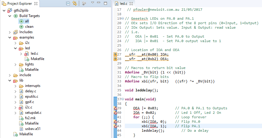
Led Code

Here is the code use for the ‘leds’ example. It deliberately doesn’t use the gtfx2lplib files as to allow a base example of whats happening. There is also the ‘lights’ code, which uses the library itself to run its functions.

1
2
3
4
5
6
7
8
9
10
11
12
13
14
15
16
17
18
19
20
21
22
23
24
25
26
27
28
29
30
31
32
33
34
35
36
37
// Geeetech LEDs on PA.0 and PA.1
// OEx sets I/O Direction of the 8 port pins (0=Input, 1=Output)
// IOx Output: Sets value. Input & Output: read value
// i.e.
//   OEA |= 0x01  - Set PA.0 to Output
//   IOA |= 0x01  - Set PA.0 output value to 1
 
// Location of IOA and OEA
__sfr __at(0x80) IOA;
__sfr __at(0xb2) OEA;
 
// Macros to return bit value
#define _BV(bit) (1 << (bit))
// Macro to flip bits
#define xbi(sfr, bit)   ((sfr) ^= _BV(bit))
 
void leddelay();
 
void main(void)
{
    OEA |= 0x03;        // PA.0 & PA.1 to Outputs
    IOA = 0x02;         // Led 1 Off, Led 2 On
    for (;;) {          // Loop forever
        xbi(IOA, 0);    // Flip PA.0
        xbi(IOA, 1);    // Flip PA.1
        leddelay();     // Do a delay
    }
}
 
// Some code to provide a delay
void leddelay()
{
    int i = 0,k = 0;
    for(i = 0;i < 1000;i++) {
        for(k = 0;k < 100; )k++;
    }
}

Deploying to EEPROM

To keep your code int eh device beyond a power down or reset, the code needs to be deployed to the EEPROM. To do so:

  1. Ensure jumper J2 is in place
  2. Reset the device (power cycle or press reset button)
  3. Remove jumper J2, this will enable the EEPROM, but as the chips is powered, it won’t read its code from it)
  4. Open EZUSB (Start menu or “CyConsole.exe EZ”
  5. Click on the ‘Lg EEPROM’.
  6. Navigate to examples\leds, select leds.iic, click ok
  7. EZUSB will now copy the code to the EEPROM instead of RAM
  8. Once complete, press the reset button. Code will be loaded from EEPROM

The above procedure must be repeated each time you wish to program the EEPROM (i.e. replace the jumper, reset, remove jumper, program. I find it easier to do inital development work using just RAM, and then program the EEPROM with code when im ready to more production style testing.

Ebay Cheapies: Arduino Mega and 8×8 LED Matrix w/MAX7219 + ‘Saleae’ Logic Analyzer

 Ebay Cheapies 001

A couple of my ebay cheap buys have arrived. I have an Arduino Mega for $12, and a 8×8 LED Matrix with a (fake) MAX7219 driver for $3. To test them out, i’ve hooked them both up, and wrote some Arduino code to show what they can do.

I usually don’t use Arduino for Projects, but for testing out some parts it works great! Don’t even have to get my MKII programmer out fo the drawer.

Also as a bonus, my knock off Saleae Logic Anayzler ($10) has arrived. I’ve used it to plot out the logic of shifting the data from the Arduino to the MAX7219.

Not much else to say here, so lets get into some pictures, code, and a video!

MAX7219 kit: Pretty simple setup here, the MAX7219 provides 3 data lines to the arduino, which allows the 8×8 matrix to set which leds are to be lit.

ledmatrix_partsledmatrix

Arduino Mega: The back and front of the Arduino Mega. Amazing value at $10, considering the retail price of the non-clone is like $70. The only difference i could tell is the back of the PCB looks to say ‘ROARD’ instead of ‘BOARD’.

mega_frontmega_reverse

‘Saleae’ Logic Anazlyer: A $10 rip off of the Saleae system. Looks nothing like the quite refined Saleae logic, but does the job quite well. Uses the official software form Saleae. Read somewhere that this can be reconfigured to use the USBee software also, but havn’t had a chance to look at that yet.

saleae_clone03


saleae_clone02


Here is a screen shot showing the analyzer in use, channel description:

  1. MAX7219 Clock line
  2. MAX7219 Load line
  3. MAX7219 Data line
  4. Custom line to show pushing out an entire 8×8 led update

saleae_logic

Here is the video showing a quick demostration of using the MAX7219 kit and the Arduino Mega


And finally, the code for doing this. The MAX7219 code has been ripped from the arduino.cc website. The rotary code is my own, which you can read more about in this post here. This will also work on a standard Arduino (clones available on the net form $8!)

You can also find the lastest version of this code on my SVN repo here.

** RECOMMEND using the above WebSVN link until i sort out my Syntax Highligter

1
2
3
4
5
6
7
8
9
10
11
12
13
14
15
16
17
18
19
20
21
22
23
24
25
26
27
28
29
30
31
32
33
34
35
36
37
38
39
40
41
42
43
44
45
46
47
48
49
50
51
52
53
54
55
56
57
58
59
60
61
62
63
64
65
66
67
68
69
70
71
72
73
74
75
76
77
78
79
80
81
82
83
84
85
86
87
88
89
90
91
92
93
94
95
96
97
98
99
100
101
102
103
104
105
106
107
108
109
110
111
112
113
114
115
116
117
118
119
120
121
122
123
124
125
126
127
128
129
130
131
132
133
134
135
136
137
138
139
140
141
142
143
144
145
146
147
148
149
150
151
152
153
154
155
156
157
158
159
160
161
162
163
164
165
166
167
168
169
170
171
172
173
174
175
176
177
178
179
180
181
182
183
184
185
186
187
188
189
190
191
192
193
194
195
196
197
198
199
200
201
202
203
204
205
206
207
208
209
210
211
212
213
214
215
216
217
218
219
220
221
222
223
224
225
226
227
228
229
230
231
232
233
234
235
#include <Encoder.h>
 
// Delays for certain events in ms
const int ROTARY_DELAY = 100;    // Time between checking for rotary turns
const int BUTTON_DELAY = 800;    // Button debouncing, and repeating
const int FLASH_DELAY = 600;     // How long to flash the entire row after button press
const int CURSOR_DELAY = 200;    // How quickly to flash the cursor led
 
// Pin Assignments
uint8_t rota = 2;
uint8_t rotb = 3;
uint8_t button = 4;
uint8_t dataIn = 5;
uint8_t load = 6;
uint8_t clock = 7;
uint8_t trigger = 12;
 
int maxInUse = 1; 
uint8_t x = 0;
 
byte max7219_reg_noop        = 0x00;
byte max7219_reg_digit0      = 0x01;
byte max7219_reg_digit1      = 0x02;
byte max7219_reg_digit2      = 0x03;
byte max7219_reg_digit3      = 0x04;
byte max7219_reg_digit4      = 0x05;
byte max7219_reg_digit5      = 0x06;
byte max7219_reg_digit6      = 0x07;
byte max7219_reg_digit7      = 0x08;
byte max7219_reg_decodeMode  = 0x09;
byte max7219_reg_intensity   = 0x0a;
byte max7219_reg_scanLimit   = 0x0b;
byte max7219_reg_shutdown    = 0x0c;
byte max7219_reg_displayTest = 0x0f;
 
 
Encoder knobLeft(rota, rotb);
 
 
char id=0;
 
void putByte(byte data) {
  byte i = 8;
  byte mask;
  while(i > 0) {
    mask = 0x01 << (i - 1);      // get bitmask
    digitalWrite( clock, LOW);   // tick
    if (data & mask){            // choose bit
      digitalWrite(dataIn, HIGH);// send 1
    }else{
      digitalWrite(dataIn, LOW); // send 0
    }
    digitalWrite(clock, HIGH);   // tock
    --i;                         // move to lesser bit
  }
}
 
void maxSingle( byte reg, byte col) {    
//maxSingle is the "easy"  function to use for a     //single max7219
 
  digitalWrite(load, LOW);       // begin    
  putByte(reg);                  // specify register
  putByte(col);//((data & 0x01) * 256) + data >> 1); // put data  
  digitalWrite(load, LOW);       // and load da shit
  digitalWrite(load,HIGH);
}
 
void maxAll (byte reg, byte col) {    // initialize  all  MAX7219's in the system
  int c = 0;
  digitalWrite(load, LOW);  // begin    
  for ( c =1; c<= maxInUse; c++) {
  putByte(reg);  // specify register
  putByte(col);//((data & 0x01) * 256) + data >> 1); // put data
    }
  digitalWrite(load, LOW);
  digitalWrite(load,HIGH);
}
 
void maxOne(byte maxNr, byte reg, byte col) {    
//maxOne is for adressing different MAX7219's,
//whilele having a couple of them cascaded
 
  int c = 0;
  digitalWrite(load, LOW);  // begin    
 
  for ( c = maxInUse; c > maxNr; c--) {
    putByte(0);    // means no operation
    putByte(0);    // means no operation
  }
 
  putByte(reg);  // specify register
  putByte(col);//((data & 0x01) * 256) + data >> 1); // put data
 
  for ( c =maxNr-1; c >= 1; c--) {
    putByte(0);    // means no operation
    putByte(0);    // means no operation
  }
 
  digitalWrite(load, LOW); // and load da shit
  digitalWrite(load,HIGH);
}
 
 
void setup () {
  pinMode(dataIn, OUTPUT);
  pinMode(clock,  OUTPUT);
  pinMode(load,   OUTPUT);
  pinMode(button, INPUT);
  pinMode(trigger, OUTPUT);
  digitalWrite(button, HIGH);
  digitalWrite(13, LOW);  
  digitalWrite(trigger, LOW);
 
  //initiation of the max 7219
  maxAll(max7219_reg_scanLimit, 0x07);      
  maxAll(max7219_reg_decodeMode, 0x00);  // using an led matrix (not digits)
  maxAll(max7219_reg_shutdown, 0x01);    // not in shutdown mode
  maxAll(max7219_reg_displayTest, 0x00); // no display test
  for (x=1; x<=8; x++) {    // empty registers, turn all LEDs off
    maxAll(x,0);
  }
  maxAll(max7219_reg_intensity, 0x01 & 0x0f);  // the first 0x0f is the value you can set range: 0x00 to 0x0f
 
}  
 
// Value to display a single LED on a row
uint8_t values[9] = {0, 1, 2, 4, 8, 16, 32, 64, 128};
// Array with all rows, indicating which 'value' to show
uint8_t line[8] = {0, 0, 0, 0, 0, 0, 0, 0}; 
// What row we are current working with
uint8_t idx = 0;
// Our delay counters (in ms)
int delayButton = 0;
int delayRotary = ROTARY_DELAY;
int delayFlash = 0;
int delayCursor = CURSOR_DELAY;
int cursorState = 0;
 
// Rotary position, reset after each loop
long pos = 0;
// Do we update the matrix this run?
uint8_t update = 1;
 
void loop () { 
 
  // Flash the row after a button press
  if (delayFlash && idx != 8) {
    maxSingle(idx+1, 255);
 
    if (delayFlash == 1) {
      maxSingle(idx+1, values[line[idx+1]]);
    }
 
    delayFlash--;
    if (delayButton) delayButton--;
 
    return;
  } 
 
  // Check for button press
  if (delayButton) delayButton--;
  if (!digitalRead(4) && delayButton == 0) { 
    if (idx == 8) 
      idx = 0;
     else
       idx++;
     delayButton = BUTTON_DELAY;
     delayFlash = FLASH_DELAY;
  }
 
 
  // Checks for rotary turning, and update
  //  the matrix buffer
  // My rotary encoder had '2 turns' per detent, making
  //  it awkward to move a single position. This is why
  //  the check is for > 1 and < -1 to make it a full detent.
  if (delayRotary) delayRotary--;
  if (delayRotary == 0 && idx != 8) {
    pos = knobLeft.read();
    if (pos > 1) {
      if (line[idx] != 0)
        line[idx]--;
      else
        line[idx] = 8;
      update = 1;
    } else if (pos < -1) {
      if (line[idx] != 8)
        line[idx]++;
      else
        line[idx]= 0;
      update = 1;
    }
 
    if (update) { 
      knobLeft.write(0);
      delayRotary = ROTARY_DELAY;
 
      if (pos) {
        cursorState = 1;
        delayCursor = CURSOR_DELAY;
      }
    }
  }
 
 
  // Toggle the state of the cursor after the
  //  cursor delay (in ms) has been reached
  if (delayCursor) delayCursor--; 
  if (delayCursor == 0 && idx != 8) {
    delayCursor = CURSOR_DELAY;
    cursorState = 1 - cursorState;
    update = 1; 
  }
 
  // Update the matrix only if a change has been made
  if (update) {
    for (x = 0; x<8; x++) {
       if (x == idx) {
         if (cursorState && line[x] != 0)
             maxSingle(x+1, values[line[x]]);
         else
             maxSingle(x+1, 0);
       } else {
         if (line[x] == 0) continue;
         digitalWrite(trigger, HIGH);
         maxSingle(x+1, values[line[x]]);
         digitalWrite(trigger, LOW);
       }
    }
    update = 0;
  }
 
  delay(1);
 
}

Examples – Rotary Encoders using PCINT

Introduction

This example is about using Rotary Encoders with AVR chips. In provides a brief look at what they are, and how to use them.

While searching the web for how to use rotary encoders, I came across a number of tried methods. Nearly all of them though used the hardware interrupt pins on the chip though. As i use these primarily for USB, i could not spare them for a rotary coder (let alone if when i wanted to use multiple rotary encoders!). For this reason, i developed my own solution using the Pin Change Interrupts (PCINT). These are similar to hardware interrupts, but trigger when any of the Pins enabled to use PCINT change. It is then up to the developer to discover what pins actually changed, and what the changes are.

Rotary Encoders

As usual, Wikipedia has the best definition of a Rotary Encoder:

rotary encoder, also called a shaft encoder, is an electro-mechanical device that converts the angular position or motion of a shaft or axle to an analog or digital code.

Rotary Encoders come in many shapes, forms and output types. The simpliest rotary coder looks like a potentiometer, but is continually turnable. Other have dual shafts (or two inputs), and can come with switches in built (depresses the rotary encoder closed the circuit). Some are made to be connected to large machinery and turned via engines and what not.

The ‘analog or digital code’ describes how the rotary encoder actually encodes the information we have received via input into the rotary coders (i.e. turning the encoder). The type of output we are interested in for this example are those that output in ‘Quadrature’.

Quadrature is two signal that is 90 degrees out of phase with each other. That means that the direction of the turn can be indicated by which of the signals changed first (and the 2nd confirming the turn). The angular speed of the turn can also be indicated by the duration of the pulse. However, for this project, we are only going to look at which way the encoder is turning.

To learn more about quadrature, i suggest reading my previous post detailing how to make a Quadrature Generator.

Example Code and Schematic

For this example, i’ve used the ATTiny2313 chip. Any AVR will do, but you will need to update the code with the correct ports to make it work with other variants (Even the ATMega’s). The 2313 series is a cheap chip for development, but with only 2K of program memory, it seriously limits what you can do with it (Even the newly released 4313 with 4K of PROGMEM is very limiting).

The example im showing here has the rotary encoder as the input, a 3 leds as outputs. The leds function like this:

  • LED1: Indicates the rotary encoder was turned in a direction.
  • LED2: Indicates the rotary encoder was turned in the opposite direction to LED1.
  • LED3: Indicates that an pin change interrupt has been received by the chip.

Rotary Encoder Schematic

Download: The Eagle schematic here

Below is the code for the example. This code can also be viewed on my SVN Repo. The avr-gcc Makefile is also available in the SVN repo.

1
2
3
4
5
6
7
8
9
10
11
12
13
14
15
16
17
18
19
20
21
22
23
24
25
26
27
28
29
30
31
32
33
34
35
36
37
38
39
40
41
42
43
44
45
46
47
48
49
50
51
52
53
54
55
56
57
58
59
60
61
62
63
64
65
66
67
68
69
70
71
72
73
74
75
76
77
78
79
80
81
82
83
84
85
86
87
88
89
#include <stdint.h>
#include <avr/pgmspace.h>
#include <avr/io.h>
#include <avr/interrupt.h>
#include <avr/wdt.h>
 
#define F_CPU 12000000
#include <util/delay.h>
 
#define DEPRESS_TIME    1
 
#define sbi(sfr, bit)   ((sfr) |= _BV(bit))             // Set bit 
#define cbi(sfr, bit)   ((sfr) &= ~(_BV(bit)))          // Clear bit
#define xbi(sfr, bit)   ((sfr) ^= _BV(bit))             // Flip bit
#define rbi(sfr, bit)   (((sfr) >> (bit)) & 0x01)
 
volatile uint8_t pcIntCurr = 0;
volatile uint8_t pcIntLast = 0;
volatile uint8_t pcIntMask = 0;
 
volatile uint8_t timer0_ovf = 0;
volatile uint8_t time_rot = 0;
 
void doInt();
 
int main() {
        cbi(DDRB, PCINT2);
        cbi(DDRB, PCINT3);
 
        TIMSK = (1<<TOIE0);                   // Eable timer overflow for Timer0
        TCNT0 = 0x00;                         // Set Timer0 to 0
        TCCR0B = (1<< CS02) | (1<<CS00);      // /1024 prescaler
 
        PORTB |= (( 1 << PCINT2 ) | ( 1 << PCINT3 )); //turn on pullups
        PCMSK |= (( 1 << PCINT2 ) | ( 1 << PCINT3 )); //enable encoder pins interrupt sources
        sei();
        GIMSK |= ( 1 << PCIE ); //enable pin change interupts
 
        DDRD |= ( 1 << PD4 );
        DDRD |= ( 1 << PD5 );
        DDRD |= ( 1 << PD6 );
 
        sbi(PORTD, PD6);
        _delay_ms(1000);
        cbi(PORTD, PD6);
 
        for (;;) {
 
                if (!time_rot) {
                        cbi(PORTD, PD4);
                        cbi(PORTD, PD5);
                }
 
                if (pcIntMask)
                        doInt();
        }
}
 
void doInt() {
  xbi(PORTD, PD6);
 
  if (rbi(pcIntCurr, PCINT2) == 0 && rbi(pcIntCurr, PCINT3) == 0 && rbi(pcIntMask, PCINT2) ) {
        cbi(PORTD, PD5);
        sbi(PORTD, PD4);
        time_rot = 5;
  } else if (rbi(pcIntCurr, PCINT3) == 0 && rbi(pcIntCurr, PCINT2) == 0 && rbi(pcIntMask, PCINT3) ) {
        cbi(PORTD, PD4);
        sbi(PORTD, PD5);
        time_rot = 5;
  }
 
  pcIntMask = 0;
}
 
ISR(TIMER0_OVF_vect) {
        timer0_ovf++;
 
        if (time_rot) {
                time_rot--;
        }
}
 
 
ISR(PCINT_vect)
{
  pcIntCurr = PINB;
  pcIntMask = pcIntCurr ^ pcIntLast;
  pcIntLast = pcIntCurr;
}

Conclusion

Here are the Bitscope Logic outputs dumps for the rotary being turned in either direction. This is actually using the Quadrature Generator to provide input. This is a great way to test the rotary code, and is also great for testing how fast the MCU can detect changes. The definition of each of the traces are:

  1. WHITE – Rotary Encoder A Input.
  2. BROWN – Rotary Encoder B Input.
  3. RED – Clock signal from the Quadrature Generator.
  4. ORANGE – A DIR2 turn event occurred.
  5. YELLOW – A DIR1 turn event occurred.
  6. PURPLE – A Pin Change Interrupt (PCINT) occurred.

Rotary Encoder direction 1

Rotary Encoder direction 2


Gallery of all images in this post: