Introduction
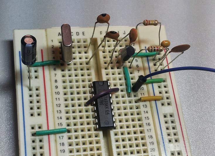
Colpitts Oscillator, with AY38910 PSG in background
Clock sources are used in pretty much all digital electronics these days. There are many ways to create clock sources, from a simple 555 timers, to using a micro-controller (PIC, AVR) to output a clock source. I had a specific need for a 2MHz clock source to drive an AY38910 programmable sound generator chip I had ordered off ebay.
After looking through my surplus crystal, the lowest speed I could find was a 4Mhz crystal. Using that as a starting point, I went searching for how to quickly put it to use to get a stable and accurate signal. For this, i came across the Colpitts Oscillator.
Wikipedia describes the Colpitt Oscillator as:
A Colpitts oscillator, invented in 1918 by American engineer Edwin H. Colpitts, is one of a number of designs for LC oscillators, electronic oscillators that use a combination of inductors (L) and capacitors (C) to produce an oscillation at a certain frequency. The distinguishing feature of the Colpitts oscillator is that the feedback for the active device is taken from a voltage divider made of two capacitors in series across the inductor.
The Colpitts Oscillator Circuit
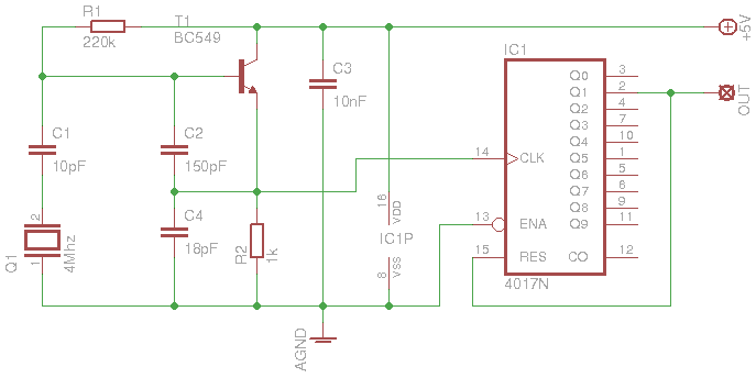
So after reviewing some circuit diagrams, and resistor/capacitor values, i came up with this circuit for generating a stable 4Mhz square wave.
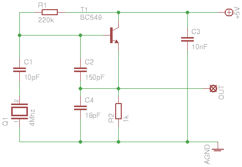
4MHz Colpitts Oscillator
Download: The CADSoft Eagle schematic here
This all seemed to work pretty well. I pestered around with bumping up to 8Mhz, which worked with a bit of degradation on the amplitude of this signal. 12MHz had the output so low it wouldn’t drive TTL inputs. Given i was after a fairly low frequency, i didn’t investigate why i couldn’t get to higher speeds. The Colpitts Oscillator should be able to get up to about 20Mhz.
Its time to measure up the frequency of the output. I was a little annoyed at the latest update of the Bitscope DSO software. usually, the cursor frequency shows in the bar down the bottom, but now its in the left hand side bar… which isn’t included in the ‘save as image’ function.
So here is the signal output on the oscilloscope. You’ll have to take my word for it that the cursor (Vertical lines) indicates a 4MHz something resembling a sine wave.
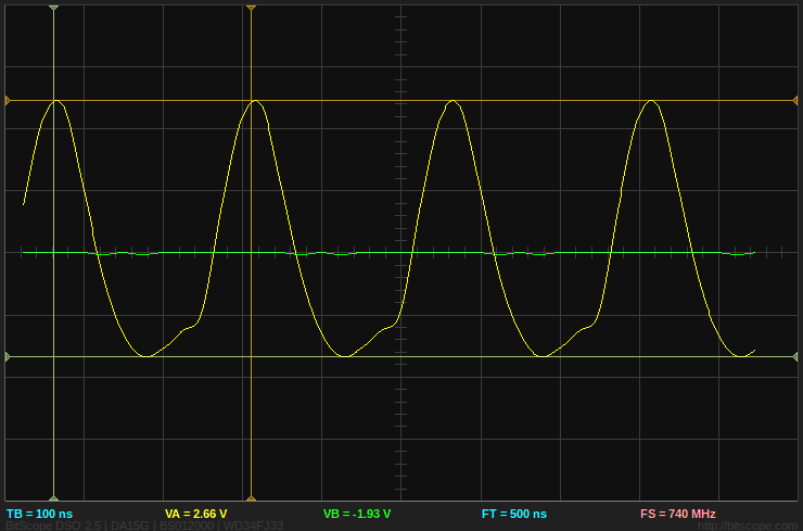
Colpitts Oscillator outputting a 4MHz signal
Creating a 2MHz Signal, with a CMOS 4017 Decade Counter
At the start of this post, you may remember saying that the AY38910 PSG required 2MHz (Or more correctly, between 1 and 2 MHz). You might also remember be saying that the lowest frequency crystal I had was 4MHz. All true. So the question now is how do I get the 4MHz output from the Colpitts Oscillator down to the 2MHz required by the PSG.
I searched around the net for a solution, and most seemed to revolve around using a J-K type Flip-Flop. Havnt not any of these in stock, I remembered an old trick used a while back: Using a CMOS 4017 decade counter with 2nd clock counter pin connected to the reset pin. Thus when the reset pin is triggered, that becomes your ‘divided by two’ output.
This can be used to divide to get all sorts of lower frequencies, i.e.
- 4 / 2 = 2.00 MHz
- 4 / 3 = 1.33 MHz
- 4 / 4 = 1.00 MHz
- 4 / 5 = 0.80 MHz
- and so on…
So with the above in mind, I modified the 4 MHz Colpitts Oscillator to look like this:
Download The CADSoft Eagle schematic here
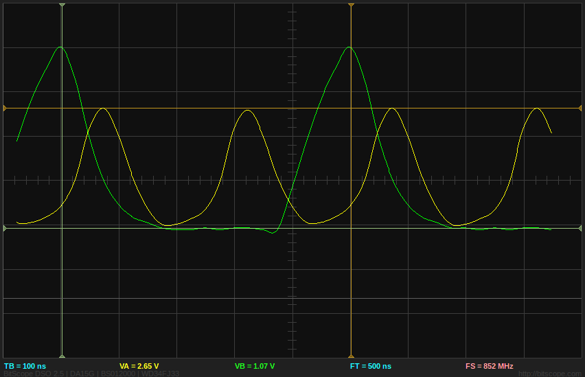
Using the CMOS chip had the added benefit of restoring the rather weak signal from the T1 transistor to the full 5V level (Im guessing this is due to the BC549 transistor’s base not being loaded to near saturation, if anyone can improve this, let me know!). The below oscilloscope screenie shows the yellow trace as the Colpitts output, and the green trace the output from the 4017. Once again you’ll have to take my word that the yellow is 4 MHz, and the green is 2 MHz.
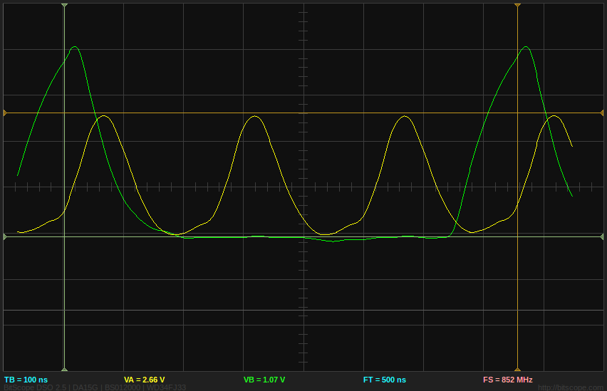
And here is one more showing 1.33 MHz. I ended up using 1.33 MHz to clock the PSG, as the sound produced was a bit more crisp. It’s also the frequency that GIC use for their example circuits in the PSG Data Manual (The best source of info for the AY38910!)
Conclusion
The Colpitts driver is a nice way to generate a stable and accurate clock signal. Truth be told though, its probably much easier just to use a can resonator. It was a nice break from digital electronics though, i dont often get to use the oscilloscope part of my BitScope.
I’ll leave here with a sneak peak video of the Colpitts Oscillator clocking the AY38910 to play… the Overworld Mario Bros. theme song!!. This project will be published here in the next couple of weeks. Its using an arduino to program the PSG, which i’ll be replacing with a straight AtMega168 (I dont use arduino for finished projects).
httpv://www.youtube.com/watch?v=JdQvEOVhZCo
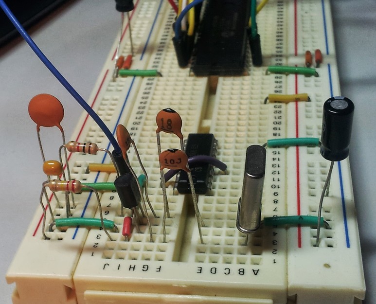
And another picture of the Colpitts Oscillator driving the AY38910 PSG