PIC 16F84 Master and 16F88 Slave
This was my first attempt at doing I2C. I decided to get 2 PIC micros talking to each other. The 16F84 was the first chips i started using, which was easy to do for the Master. The slave however was a totally different beast, bit banging methods didn't work.
The PIC16F88 comes with an inbuilt SSP module that allows I2C communcation to be handled via the firmware. This makes life a lot easier when detecting start and finish commands.
The Plan
Simple enough: Have the 16F84 send I2C data to the 16F88 and have it prove that its received it. FOr a simple test, a number will be incremented on the master, sent via I2C to the salve. It will then use a LED to show the highest bit set. This will happen when the incremented number is greater then 0x80. When the number carries over to 0x00, it will be reset.
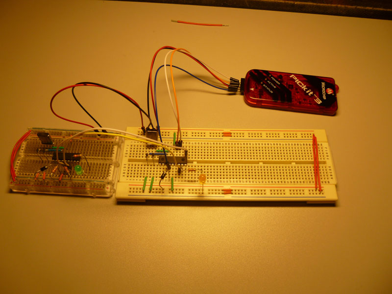
To jump ahead a little, here is the finished product on the prototyping board:

This image show the finished product. The 16F84 'master' is on the left, the 16F88 'slave' on the right. The green LED on the master will flash for the duration of a send command (At 4Mhz, its a solid). I use this as the trigger on the logic analyser to get better detail about whats happening. The orange LED on the slave will only be lit when the master's counter is larger then 0x80.
'Master'
Creating the master was the simple part. I borrow heavily from here . This guy has created a great example of how to read and write from a port expander. This will be my next project when the port expander arrives from Little Bird Electronics . I mostly re-wrote all the code while referencing the original. The 'SendCount' label is the guts of the program, sending the currently held number over the I2C bus.
Another note here is the line #define I2C_SLAVE1 0x27. I have defined the address as 0x27, but on the slave it will be left-shifted, so the address on the slave side must be 0x43. I'll get around to addressing that eventually.
Here is the code verbatim
    list        p=16F84A
    include    "p16F84a.inc"

;***** CONFIGURATION
           __CONFIG _PWRTE_ON & _HS_OSC & _WDT_OFF

; pin assignments
    #define SDA         0           ; Pin 0
    #define SCL         1           ; Pin 1
    #define TRIS_SDA    TRISB,SDA
    #define TRIS_SCL    TRISB,SCL
    #define I2C_SDA     PORTB,SDA
    #define I2C_SCL     PORTB,SCL
    #define LED         PORTB,2

    #define I2C_SLAVE1 0x27

    CBLOCK     0CH
        counter

        _I
        byte_send
        i2c_addr

        i2c_ret         ; I2C Return Value

        dly_loop1       ; Loops for delays
        dly_loop2
    ENDC

    ORG 0
    goto start           ; jump over to main routine

;***** Initialisation
start
        ; configure ports
        clrw                    ; configure PORTB and PORTC as all outputs
        tris    PORTB
        clrf    PORTB

        movlw   b'00000000'     ; Init our counter
        movwf   counter

;***** Main loop
main_loop
        bsf     LED
        call    SendCount
        bcf     LED

        goto    main_loop

SendCount

        movlw   I2C_SLAVE1      ; 7-bit address of dev
        bcf     STATUS,C        ; Use Write mode ('0')
        call    I2C_Start       ; Start a transmission
        call    ReadAck         ; Wait for Ack from slave
        movf    i2c_ret         ; Check return value
        btfss   STATUS,Z        ; Goto SendEnd on NACK
        goto    SendErr

        movfw   counter         ; Copy byte to write (counter) to w
        call    I2C_Write       ; Write the byte to the line
        call    ReadAck            ; Should read byte from bus here
                                ;  checking that its a Nack

        call    I2C_End         ; End the packet
        bcf     LED
        incf    counter,f
        call    Delay_Short
        return

SendErr
        call    I2C_End

        ;call    Delay_Long      ; Wait a while before resend
        return

I2C_Start
        movwf   i2c_addr        ; Save the address in W
        rlf     i2c_addr,f      ; Attach '0' to 8th bit
        call    Start           ; Start the Trans
        movfw   i2c_addr
        call    I2C_Write       ; Write byte to port
        return

I2C_End
        call    Stop
        return

I2C_Write
        movwf   byte_send
        movlw   .8              ; 8 bits to send
        movwf    _I
_WriteBit
        rlf     byte_send,f        ; Move highest bit to C
        btfss   STATUS,C        ; If 'C' is clear
        call    SDA_Low         ;   -> Set data low
        btfsc   STATUS,C        ; If 'C' is set
        call    SDA_High        ;   -> Set data high

        call    SCL_Pulse

        decfsz  _I,f        ; Decrement counter, if not clear
        goto    _WriteBit         ;   -> Send next bit
        call    SDA_Low         ; Set low to allow slave to write
        return

Nack                            ; Clock a high SDA
        call    SDA_High
        call    SCL_Pulse
        return

Ack                            ; Clock a high SDA
        call    SDA_Low
        call    SCL_Pulse
        return

ReadAck
        call    SCL_High
        clrf    i2c_ret
        btfsc   I2C_SDA
        bsf     i2c_ret,0
        call    SCL_Low
        return

Start
        call    SDA_High
        call    SCL_High
        call    SDA_Low
        call    SCL_Low
        return

Stop                            ; Bring SDA high while Clock high
        call    SCL_Low
        call    SDA_Low
        call    SCL_High
        call    SDA_High
        return

SCL_Pulse
        call  SCL_High
        call  SCL_Low
        return

SDA_High
        bsf     STATUS,RP0      ; Bank 1
        bsf     TRIS_SDA        ; Make SDA pin input
        bcf     STATUS,RP0      ; Back to bank 0
        call    Delay_Short
        return

SDA_Low
        bcf     I2C_SDA
        bsf     STATUS,RP0
        bcf     TRIS_SDA        ; Make SDA pin output
        bcf     STATUS,RP0
        call    Delay_Short
        return

SCL_High
        bsf     STATUS,RP0      ; Bank 1
        bsf     TRIS_SCL        ; Make SDA pin input
        bcf     STATUS,RP0      ; Back to bank 0
        call    Delay_Short
        return

SCL_Low
        bcf     I2C_SCL
        bsf     STATUS,RP0
        bcf     TRIS_SCL        ; Make SDA pin output
        bcf     STATUS,RP0
        call    Delay_Short
        return

Delay_Short                 ; 25us delay
        movlw   .5
        movwf   dly_loop2
Delay_Short_1
        nop
        decfsz  dly_loop2,f
        goto    Delay_Short_1
        return

Delay_Long
        movlw   .250        ; 250ms delay
        movwf   dly_loop1
Outer
        movlw   .110        ; Close to 1ms when set to .110
        movwf   dly_loop2
Inner
        nop
        nop
        nop
        nop
        nop
        nop
        decfsz  dly_loop2,f
        goto    Inner
        decfsz  dly_loop1,f
        goto    Outer
        return

END
'Slave'
The slave was a completely different beast to work with. Most code originated here , but its fairly bug ridden. It took a few hours of scouring forums to find the correct fixes. The biggest issues with the code itself where ANSEL not being cleared (leaving the pins in analogue mode), and the SDA/SCL pins not being declared as input. I'm happy to say that the code written here is completely working!
list        p=16F88
#include <p16f88.inc> ; Change to device that you are using.
	__CONFIG	_CONFIG1, _CP_OFF & _CCP1_RB0 & _DEBUG_OFF & _WRT_PROTECT_OFF & _CPD_OFF & _LVP_OFF & _BODEN_OFF & _MCLR_ON & _PWRTE_ON & _WDT_ON & _HS_OSC
	ERRORLEVEL -302
;---------------------------------------------------------------------
;Constant Definitions
;---------------------------------------------------------------------
#define NODE_ADDR 0x4e ; I2C address of this node
; Change this value to address that
; you wish to use.
;---------------------------------------------------------------------
; Buffer Length Definition
;---------------------------------------------------------------------
#define RX_BUF_LEN 8 ; Length of receive buffer
;---------------------------------------------------------------------
; Variable declarations
;---------------------------------------------------------------------
    udata_shr
    WREGsave    res 1

    udata
    STATUSsave  res 1
    FSRsave     res 1
    PCLATHsave  res 1
    Index       res 1           ; Index to receive buffer
    Temp        res 1           ;
    RXBuffer    res RX_BUF_LEN  ; Holds rec'd bytes from master
; device.
;---------------------------------------------------------------------
; Vectors
;---------------------------------------------------------------------
STARTUP code 0x00
    nop
    goto    Startup ;
    nop             ; 0x0002
    nop             ; 0x0003
    goto    ISR     ; 0x0004
PROG code
;---------------------------------------------------------------------
; Macros
;---------------------------------------------------------------------
memset macro Buf_addr,Value,Length
    movlw   Length      ; This macro loads a range of data memory
    movwf   Temp        ; with a specified value. The starting
    movlw   Buf_addr    ; address and number of bytes are also
    movwf   FSR         ; specified.
SetNext movlw Value
    movwf   INDF
    incf    FSR,F
    decfsz  Temp,F
    goto    SetNext
    endm
LFSR macro Address,Offset   ; This macro loads the correct value
    movlw   Address         ; into the FSR given an initial data
    movwf   FSR             ; memory address and offset value.
    movf    Offset,W
    addwf   FSR,F
    endm
;---------------------------------------------------------------------
; Main Code
;---------------------------------------------------------------------
Startup
    bcf     STATUS,RP1
    bsf     STATUS,RP0
    call    Setup
    banksel WREGsave
Main clrwdt ; Clear the watchdog timer.
    btfsc   RXBuffer,7
    bsf     PORTB,2
    btfss   RXBuffer,7
    bcf     PORTB,2
    goto    Main ; Loop forever.
;---------------------------------------------------------------------
; Interrupt Code
;---------------------------------------------------------------------
ISR
    movwf   WREGsave    ; Save WREG
    movf    STATUS,W    ; Get STATUS register
    banksel STATUSsave  ; Switch banks, if needed.
    movwf   STATUSsave  ; Save the STATUS register
    movf    PCLATH,W    ;
    movwf   PCLATHsave  ; Save PCLATH
    movf    FSR,W       ;
    movwf   FSRsave     ; Save FSR
    banksel PIR1
    btfss   PIR1,SSPIF  ; Is this a SSP interrupt?
    goto    $           ; No, just trap here.
    bcf     PIR1,SSPIF
    call    SSP_Handler ; Yes, service SSP interrupt.
    banksel FSRsave
    movf    FSRsave,W   ;
    movwf   FSR         ; Restore FSR
    movf    PCLATHsave,W;
    movwf   PCLATH      ; Restore PCLATH
    movf    STATUSsave,W;
    movwf   STATUS      ; Restore STATUS
    swapf   WREGsave,F  ;
    swapf   WREGsave,W  ; Restore WREG
    retfie              ; Return from interrupt.
;---------------------------------------------------------------------
Setup
;
; Initializes program variables and peripheral registers.
;---------------------------------------------------------------------
    banksel PCON
    bsf     PCON,NOT_POR
    bsf     PCON,NOT_BOR
    banksel ANSEL
    movlw   0x00
    movwf   ANSEL
    banksel Index       ; Clear various program variables
    clrf    Index
    clrf    PORTB
    clrf    PIR1
    banksel TRISB
    ;clrf    TRISB
    bsf     TRISB,4
    bsf     TRISB,6
    bsf     TRISB,1
    bcf     TRISB,2
    movlw   0x36        ; Setup SSP module for 7-bit
    banksel SSPCON
    movwf   SSPCON      ; address, slave mode
    movlw   NODE_ADDR
    banksel SSPADD
    movwf   SSPADD
    clrf    SSPSTAT
    banksel PIE1        ; Enable interrupts
    bsf     PIE1,SSPIE
    bsf     INTCON,PEIE ; Enable all peripheral interrupts
    bsf     INTCON,GIE  ; Enable global interrupts
    bcf     STATUS,RP0
    return
;---------------------------------------------------------------------
SSP_Handler

;---------------------------------------------------------------------
; The I2C code below checks for 5 states:
;---------------------------------------------------------------------
; State 1: I2C write operation, last byte was an address byte.
; SSPSTAT bits: S = 1, D_A = 0, R_W = 0, BF = 1
;
; State 2: I2C write operation, last byte was a data byte.
; SSPSTAT bits: S = 1, D_A = 1, R_W = 0, BF = 1
;
; State 3: I2C read operation, last byte was an address byte.
; SSPSTAT bits: S = 1, D_A = 0, R_W = 1 (see Appendix C for more information)
;
; State 4: I2C read operation, last byte was a data byte.
; SSPSTAT bits: S = 1, D_A = 1, R_W = 1, BF = 0
;
; State 5: Slave I2C logic reset by NACK from master.
; SSPSTAT bits: S = 1, D_A = 1, BF = 0 (see Appendix C for more information)
;
; For convenience, WriteI2C and ReadI2C functions have been used.
;----------------------------------------------------------------------
    banksel SSPSTAT
    movf    SSPSTAT,W   ; Get the value of SSPSTAT
    andlw   b'00101101' ; Mask out unimportant bits in SSPSTAT.
    banksel Temp        ; Put masked value in Temp
    movwf   Temp        ; for comparision checking.
State1:                 ; Write operation, last byte was an
    movlw   b'00001001' ; address, buffer is full.
    xorwf   Temp,W      ;
    btfss   STATUS,Z    ; Are we in State1?
    goto    State2      ; No, check for next state.....
    memset RXBuffer,0,RX_BUF_LEN ; Clear the receive buffer.
    clrf    Index       ; Clear the buffer index.
    banksel SSPBUF      ; Do a dummy read of the SSPBUF.
    movf    SSPBUF,W
    return
State2:                 ; Write operation, last byte was data,
    movlw   b'00101001' ; buffer is full.
    xorwf   Temp,W
    btfss   STATUS,Z    ; Are we in State2?
    goto    State3      ; No, check for next state.....
    LFSR RXBuffer,Index ; Point to the buffer.
    banksel SSPBUF      ; Get the byte from the SSP.
    movf    SSPBUF,W
    movwf   INDF        ; Put it in the buffer.
    incf    Index,F     ; Increment the buffer pointer.
    movf    Index,W     ; Get the current buffer index.
    sublw   RX_BUF_LEN  ; Subtract the buffer length.
    btfsc   STATUS,Z    ; Has the index exceeded the buffer length?
    clrf    Index       ; Yes, clear the buffer index.
    return
State3:                 ; Read operation, last byte was an address,
    movf    Temp,W ;
    andlw   b'00101100' ; Mask BF bit in SSPSTAT
    xorlw   b'00001100'
    btfss   STATUS,Z    ; Are we in State3?
    goto    State4      ; No, check for next state.....
    clrf    Index       ; Clear the buffer index.
    LFSR RXBuffer,Index ; Point to the buffer
    movf    INDF,W      ; Get the byte from buffer.
    call    WriteI2C    ; Write the byte to SSPBUF
    incf    Index,F     ; Increment the buffer index.
    return
State4:                 ; Read operation, last byte was data,
    banksel SSPCON      ; buffer is empty.
    btfsc   SSPCON, CKP
    goto    State5

    movlw   b'00101100'
    xorwf   Temp,W
    btfss   STATUS,Z    ; Are we in State4?
    goto    State5      ; No, check for next state....
    movf    Index,W     ; Get the current buffer index.
    sublw   RX_BUF_LEN  ; Subtract the buffer length.
    btfsc   STATUS,Z    ; Has the index exceeded the buffer length?
    clrf    Index       ; Yes, clear the buffer index.
    LFSR RXBuffer,Index ; Point to the buffer
    movf    INDF,W      ; Get the byte
    call    WriteI2C    ; Write to SSPBUF
    incf    Index,F     ; Increment the buffer index.
    return

State5:
    movf    Temp,W      ; NACK received when sending data to the master
    andlw   b'00101000' ; Mask RW bit in SSPSTAT
    xorlw   b'00101000' ;
    btfss   STATUS,Z    ;
    goto    I2CErr  ;
    return              ; If we aren’t in State5, then something is
                        ; wrong.
I2CErr nop
    banksel PORTB       ; Something went wrong! Set LED
    bsf     PORTB,2     ; and loop forever. WDT will reset
    goto    $           ; device, if enabled.
    return
;---------------------------------------------------------------------
; WriteI2C
;---------------------------------------------------------------------
WriteI2C
    banksel SSPSTAT
    btfsc   SSPSTAT,BF  ; Is the buffer full?
    goto    WriteI2C    ; Yes, keep waiting.
    banksel SSPCON      ; No, continue.
DoI2CWrite
    bcf     SSPCON,WCOL ; Clear the WCOL flag.
    movwf   SSPBUF      ; Write the byte in WREG
    btfsc   SSPCON,WCOL ; Was there a write collision?
    goto    DoI2CWrite
    bsf     SSPCON,CKP  ; Release the clock.
    return

end
Circuit
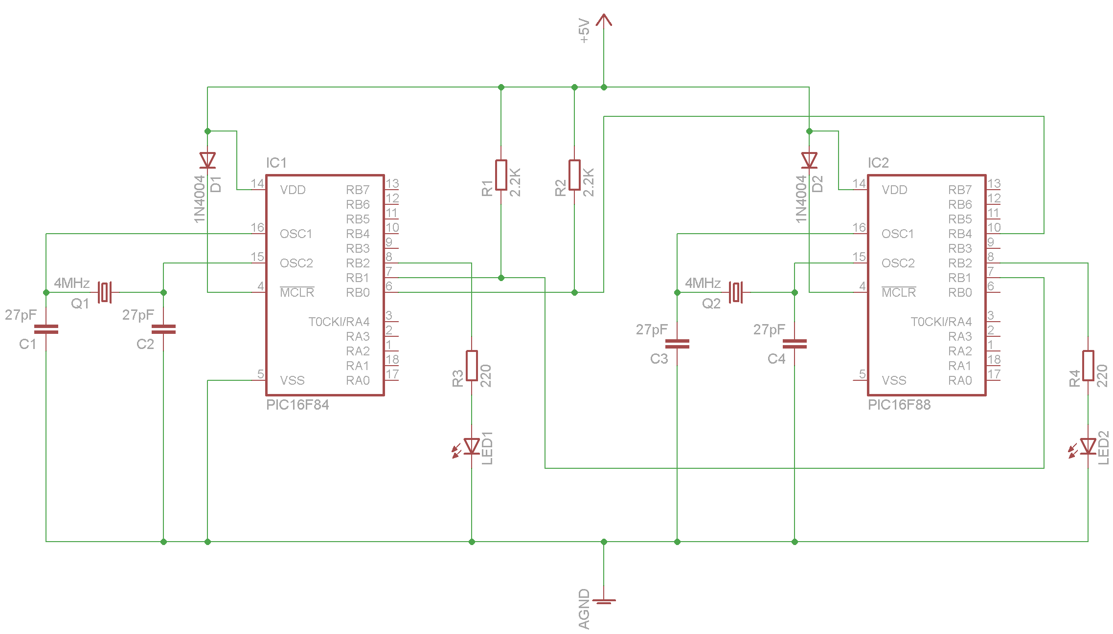
The test circuit here uses just a handful of components. The 16F88 could probably just use its own Internal 4MHz oscillator, but i havn't got around to testing that yet. Also waiting on my 10 & 20MHz crystals to arrive so i can test out higher speeds! The stabilising capacitors are really needed, but i've got a whole draw full of 29pF ceramics just sitting there so added them anyway. I also need to research if one crystal can be shared between two micro's.
As every I2C forum will tell you, ensure the pull-up resistors are installed on the SDA and SCL lines. I'm using 2.2K 1/4W resistors in the picture, but 4.7K - 10K will probably work just as well. The diodes are there for when programming the chips using the PICKit 3. Its a fairly easy matter to run a few jump leads from the PICKit to the chips one at a time. The PICKit was even able to power the circuit while testing. This meant that I would program one chip, then swap 3 leads to the other one to program it.
Here is the schematic for the circuit, simple enough. Click for larger version
Testing
Getting the timings right were critical to ensuring a good transmission. To debug it, nothing is better then using a BitScope . The picture below shows a couple of packets of I2C transmission, and the analyses of the data on the right hand side
